If you’ve ever used a GC system, you’ve almost certainly worked with an FID. And if you’ve ever wondered what actually happens inside the FID detector GC, you’re in the right place. In this casual, easy-to-follow breakdown, we’ll walk through what the FID is, what’s inside it, and how it turns burned hydrocarbons into clean, stable signals.
What Is an FID? (FID Detector GC Basics)
A Flame Ionization Detector (FID) is one of the most popular detectors in gas chromatography because it offers excellent sensitivity, a wide linear range, and predictable behavior. It works by burning sample compounds in a tiny flame. When hydrocarbons burn, they produce ions — and those ions become the electrical current that forms your chromatogram.

Although the principle seems simple, several parts must work together smoothly for the detector to stay stable and reliable.
What Makes Up an FID? (Inside the FID Detector GC)
An FID detector GC has two main sections:
- Electronic Pneumatic Controller (EPC)
- FID assembly
Let’s explore both.
EPC: The Gas Control Center of the FID Detector GC
The FID needs two essential gases:
- Hydrogen (H₂) — fuel
- Air — oxidizer
In most Agilent configurations, the EPC provides:
- Channel 1: Hydrogen
- Channel 3: Air
- Channel 2: Make-up gas (optional but very helpful)
A common flow ratio is 1:10 (H₂ : Air), typically:
- H₂ ≈ 35 mL/min
- Air ≈ 350 mL/min
 for FID Gas Control")
These flows keep the flame stable and responsive.
FID Assembly Components (Heart of the FID Detector GC)
 Assembly for Gas Chromatography")
The assembly consists of:
Igniter – Starting the Flame

The igniter provides the spark needed to ignite the hydrogen-air mix. Once the flame is burning at about 500°C, the igniter turns off automatically.
Temperature Controller – Keeping Conditions Stable
The FID body is heated to 150–250°C to:
- prevent condensation,
- stabilize the flame,
- evaporate moisture from combustion,
- keep analytes in the gas phase,
- and keep the jet clean.
Jet – Where Effluent Meets Flame

The jet has a tiny opening where hydrogen, make-up gas, and column effluent mix. Because it’s small, it improves mixing — but can clog easily.
Collector & Electrometer – Where the Signal Forms

The collector holds a negative voltage. As hydrocarbons burn, positive ions are created and pulled toward the collector. The electrometer measures the resulting picoamp-level current, which becomes the detector signal.
How the FID Generates a Signal (Step-by-Step FID Detector GC Process)
Now that the pieces make sense, let’s walk through how the FID works during a run.
1. Heating
The FID body stabilizes at about 250°C.
2. Hydrogen Flow
Hydrogen flows at ~35 mL/min.
3. Ignition
The igniter sparks briefly.
4. Air Flow
Air increases to ~350 mL/min.
You’ll often hear a small “pup” when the flame ignites.
5. Flame Verification (Lit Offset)
The GC automatically checks whether the flame is lit:
- Signal > lit offset → flame ON
- Signal < lit offset → flame OFF, ignition retries
You can verify manually: place a cool metal tool over the detector. If moisture condenses, the flame is burning.
6. Effluent Burns → Ions → Signal
Once compounds exit the column and hit the flame, they burn. Most hydrocarbons follow:
CxHy + O2 → H2O + CO2
However, a tiny fraction forms ions:
CxHy + O2 → CHO+ + e–
Those positive ions generate your FID signal.
Role of Make-Up Gas in the FID Detector GC
Make-up gas improves:
- peak sharpness,
- sweep efficiency,
- signal response.
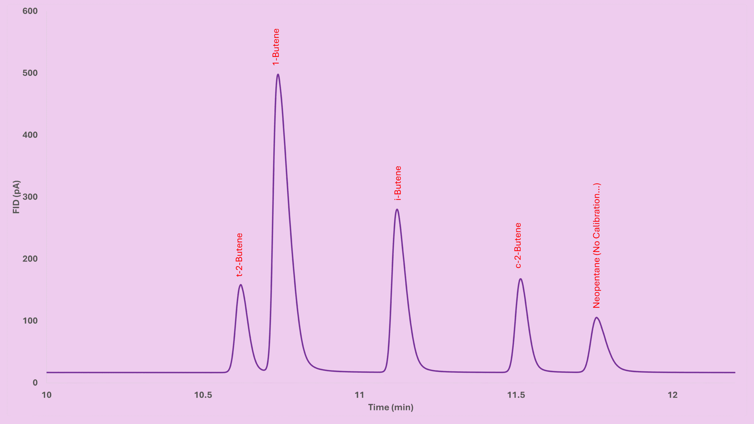
In my own tests:
- Peak area increased by ~10%
- Peaks became slightly sharper
Nitrogen works better than helium. A good range is 10–20 mL/min — but too much gas can actually blow out the flame.
Key Takeaways
- The FID detector GC burns hydrocarbons to create ions measured as current.
- It relies heavily on stable hydrogen, air, heat, and a clean jet.
- The lit offset helps the instrument confirm if the flame is truly on.
- Make-up gas improves peak shape and enhances response.
- The FID signal comes from CHO⁺ ions formed during combustion.
Before You Go
If this guide made the FID detector GC easier to understand, feel free to explore the rest of my series about Flame Ionization Detector (FID) or other GC detectors at GC Hardware section. I’m adding more practical GC content regularly, so you’ll always have something useful to bookmark or share with your teammates.