
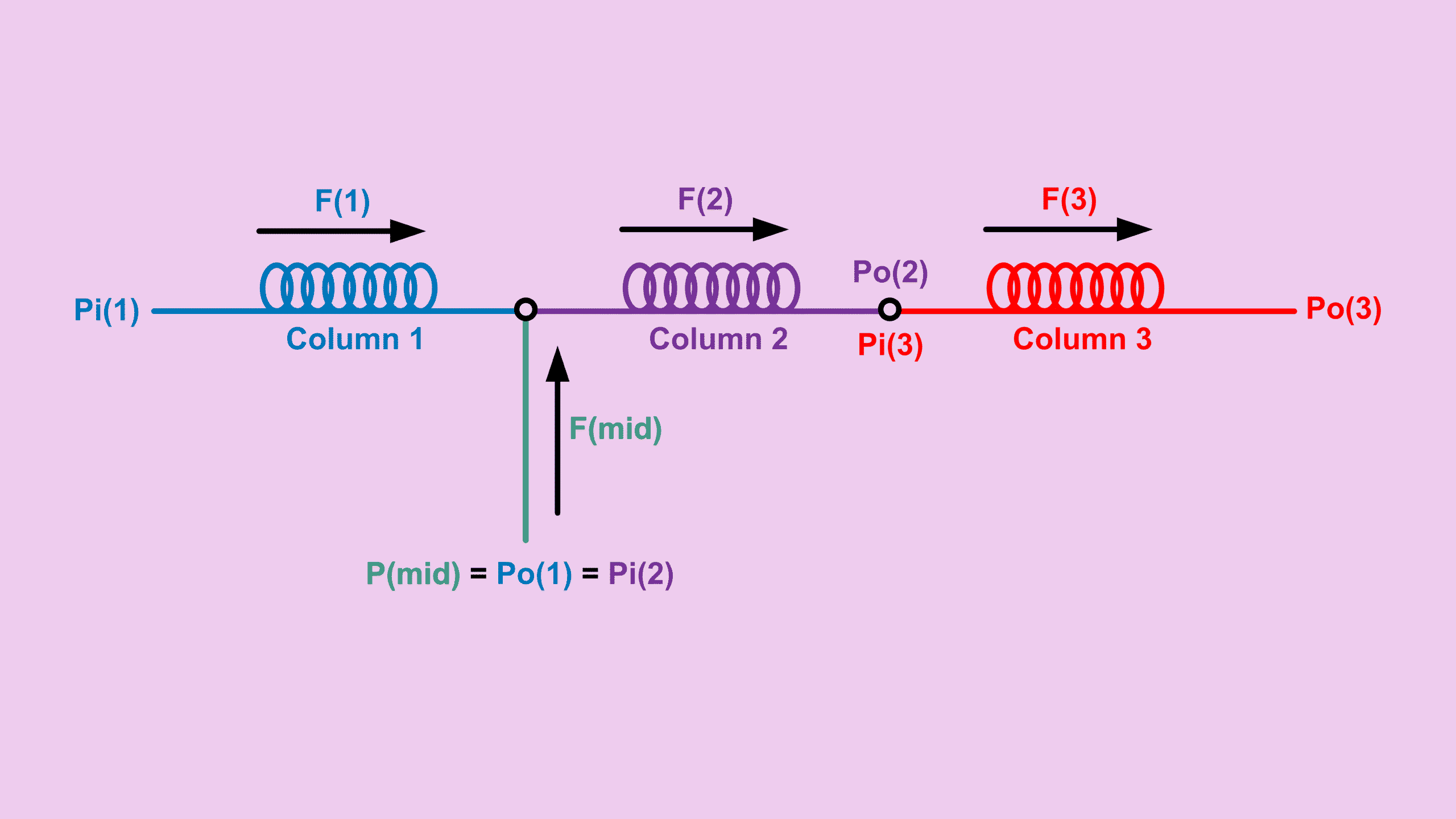
In this post we will walk through a common configuration where three columns are connected in series but at the joint of column 1 and 2 there is a pressure supply. Just like the other configuration discussed earlier for GC series columns with midpoint supply, this setup also allows backflush when the column 1 pressure is manipulated. In addition, it includes a column 3 at the end for cases where the main column 2 is temperature limited or where some specific separation is required.
When dealing with GC series columns, you may want to know how much flow travels across the three columns and how much flow is required by the midpoint supply. Therefore, in this post we will walk through the calculations step by step.
Again, we will tap on the foundation formulas below.
\[ F_o = \text{Constant} \cdot \frac{\Delta P^2}{R} \]where:
\[ \text{Constant} = 1{,}029{,}546.68 \] \[ \Delta P^2 = P_i^2 – P_o^2 \] \[ R = \frac{\eta L T_c}{d^4} \]Understanding Resistance in GC Series Columns
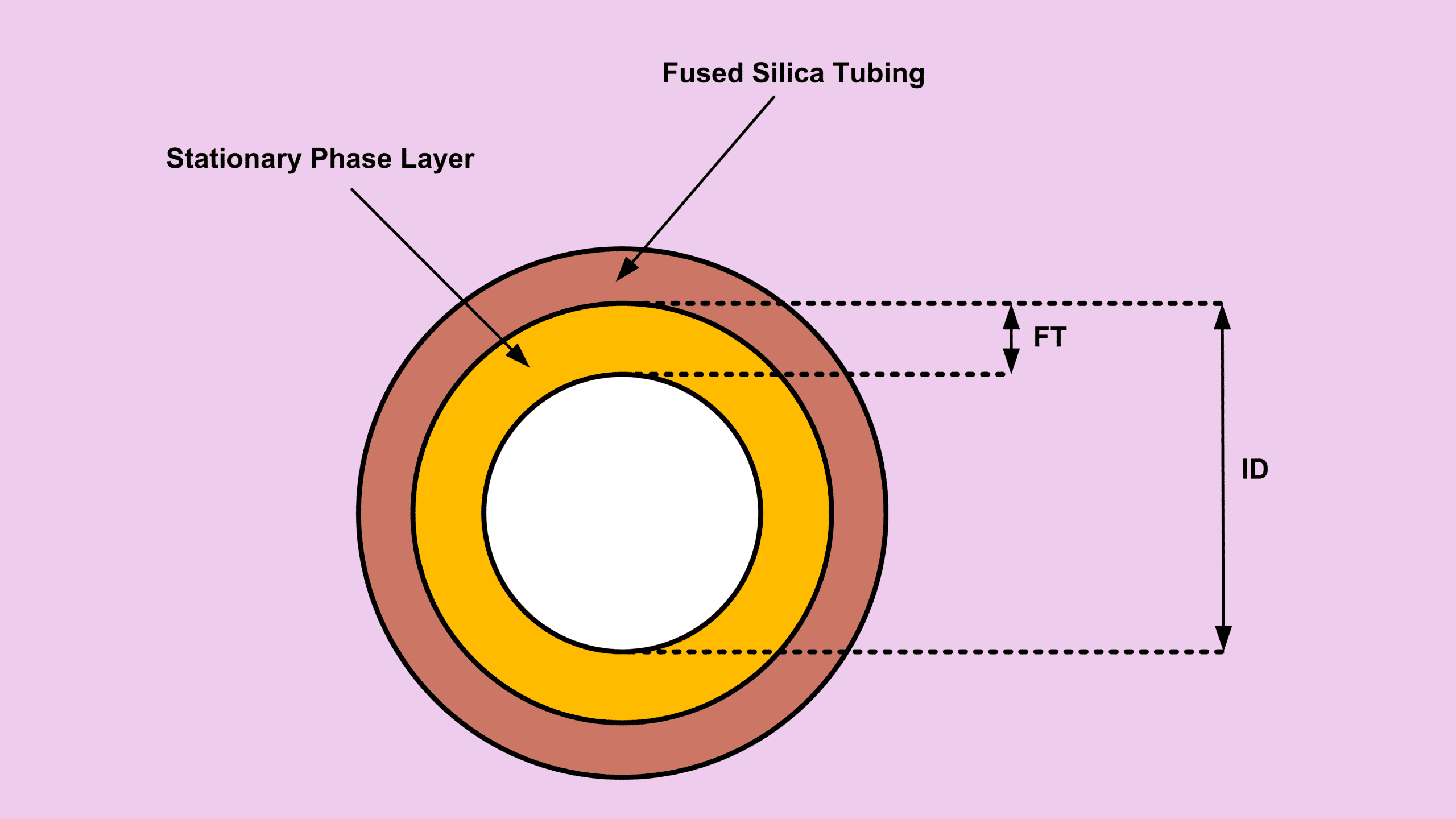
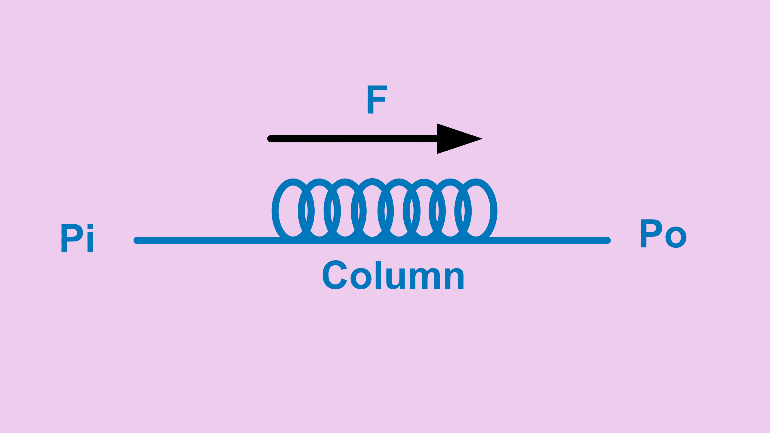
First of all, each column comes with dimensions information and temperature data. Therefore, the resistance of each column (R value) can be calculated.
So:
R1, R2 and R3 are all knownLooking at the diagram, column 2 and column 3 are in direct series without anything in between. As a result, the total resistance is simply the sum of both individual resistances.
\[ R_{(2-3)} = R_2 + R_3 \]
In this case, since we already know how much pressure is supplied at the midpoint between column 1 and column 2, that pressure is the same as the outlet pressure of column 1 and the inlet pressure of column 2.
\[ P_{mid} = P_{o(1)} = P_{i(2)} \]
At the same time, we also know $P_{i(1)}$. Therefore, we can calculate:
\[ \Delta P_1^2 = P_{i(1)}^2 – P_{o(1)}^2 \]
Calculating Flow Across GC Series Columns
We also know the outlet pressure of column 3. Now imagine combining column 2 and column 3 into a single column.
\[ \Delta P_{(2-3)}^2 = P_{i(2)}^2 – P_{o(3)}^2 \]
Knowing $\Delta P_1^2$ and $R_1$, $F_1$ can be calculated.
\[ F_1 = Constant \times \frac{\Delta P_1^2}{R_1} \]
Likewise, knowing $\Delta P_{(2-3)}^2$ and $R_{(2-3)}$, $F_{(2-3)}$ can also be calculated.
\[ F_{(2-3)} = Constant \times \frac{\Delta P_{(2-3)}^2}{R_{(2-3)}} \]
Knowing both $F_1$ and $F_{(2-3)}$, the midpoint flow becomes:
\[ F_{mid} = F_{(2-3)} – F_1 \]
Or expressed as a flow ratio:
\[ FlowRatio = \frac{F_1}{F_{(2-3)}} \]
Why Flow Ratio Matters in GC Series Columns
Typically, one should set the method so the flow ratio stays below 0.8. In other words, the flow across column 1 should be 80% or less of the flow through columns 2 and 3 combined. That means the midpoint supply contributes around 20%.
As a result, the midpoint pressure remains stable.
Think of it this way: if the column 1 flow becomes too high, columns 2 and 3 cannot consume all the incoming flow. Consequently, pressure starts building up at the midpoint or at the inlet of column 2.
What you will typically observe is that the actual pressure becomes higher than the set pressure at the midpoint. Because of that, the GC may enter a not ready status. In some cases, the difference becomes too large and the GC never reaches ready condition.
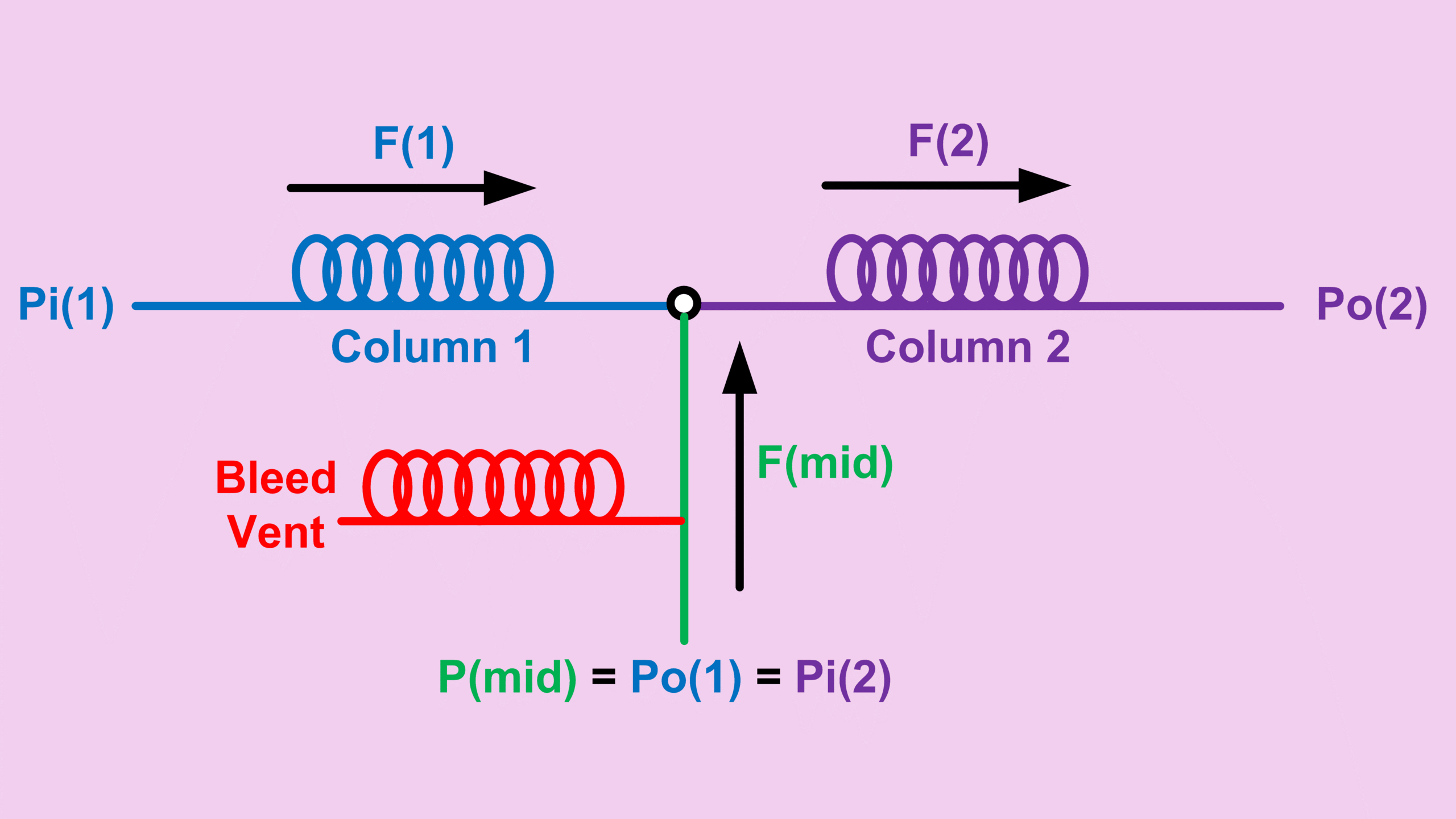
Some applications leave no choice but to run a flow ratio higher than 80%. In those situations, one could install something called a bleed vent for the midpoint pressure.
Before the midpoint pressure supply enters the connection between column 1 and column 2, the line is teed off with a restrictor to bleed off excess pressure.
Since the newer Agilent 8890 GC System models, one can purchase a PDS module with this type of bleed vent control directly through the GC software.
Determining Pressure Between Column 2 and Column 3
Knowing $F_{(2-3)}$, we also know that column 2 and column 3 are connected in series. Therefore:
\[ F_{(2-3)} = F_2 = F_3 \]
With $F_2$ and $R_2$, one can calculate $\Delta P_2^2$ from the foundation formula:
\[ F_2 = Constant \times \frac{\Delta P_2^2}{R_2} \]
Since:
\[ \Delta P_2^2 = P_{i(2)}^2 – P_{o(2)}^2 \]
We can now calculate $P_{o(2)}$, which is the midpoint pressure between column 2 and column 3.
GC Series Columns Calculator
I put them altogether in this calculator: GC 3-Series Midpoint – Three Capillary Columns.
You just need to enter:
- Column 1, 2 and 3 information
- Carrier gas
- Column 1 inlet pressure
- Column 3 outlet pressure
- Midpoint pressure
The calculator will then determine the flow behavior across the GC series columns configuration.
Key Takeaways
- GC series columns with midpoint pressure supply allow flexible flow control and backflush operation.
- Resistance values of each column are critical for accurate flow calculations.
- The midpoint flow ratio should typically stay below 0.8 for stable operation.
- Excessive flow ratio can cause midpoint pressure instability and GC not ready conditions.
- Bleed vent configurations can help stabilize midpoint pressure in difficult methods.
Explore More GC Flow Configurations
If you frequently work with capillary column configurations, midpoint pressure supply, or backflush systems, these calculations can save a lot of troubleshooting time during method development.
You can also check the related post about:
- Single column → Column Flow Calculation in GC: From Equation to Practical Use
- Two columns in series → GC Column Series Calculation: How Flow and Pressure Work Across Two Columns
- Three columns in series → GC Column Flow Series for 3 Columns Explained
- Two columns in series with mid-supply → GC Backflush Column Setup Explained (Flow Calculation Made Simple)