
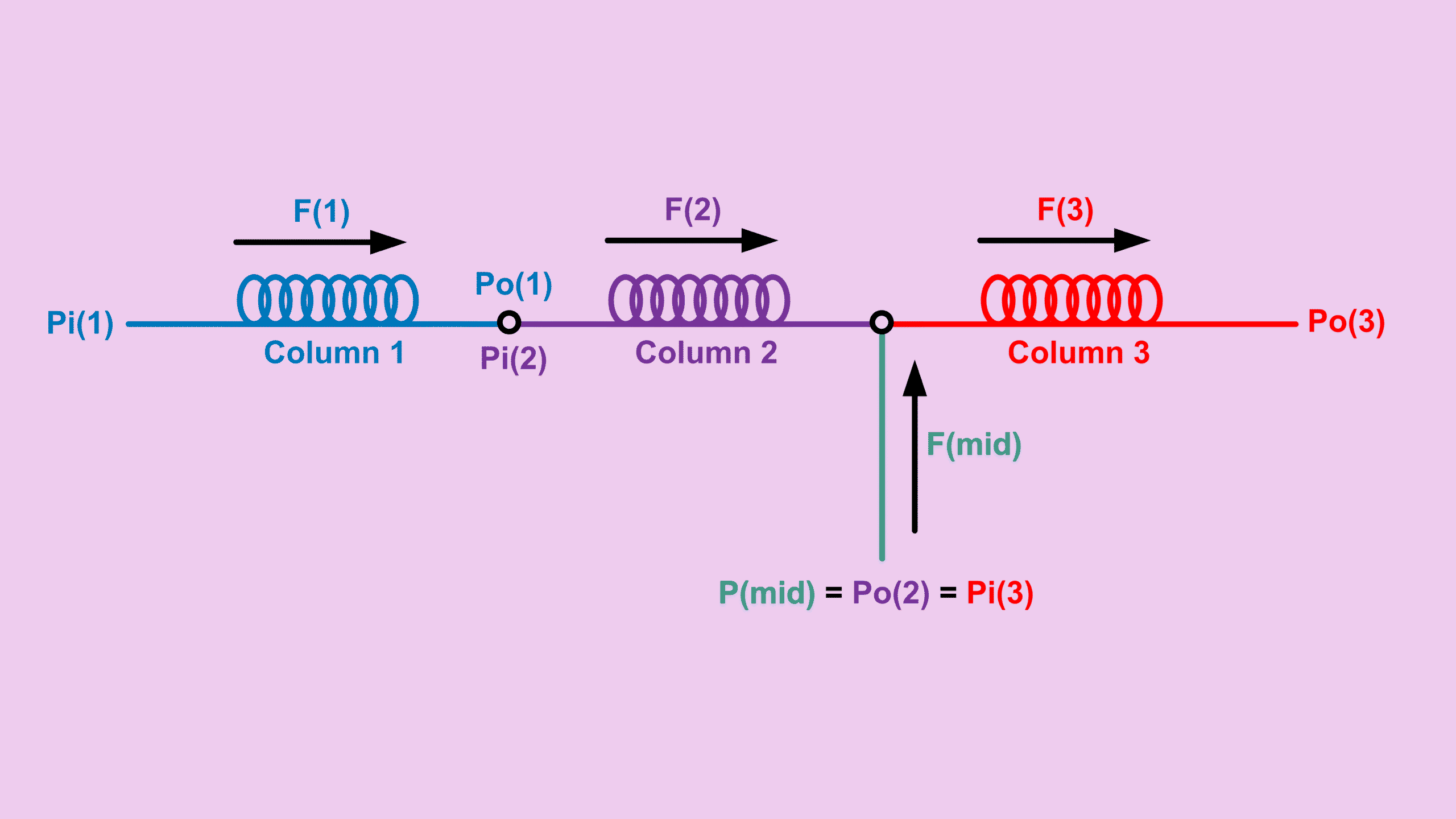
When working with a midpoint pressure GC configuration, it is common to see multiple columns connected together with an additional pressure supply introduced somewhere in the middle of the setup. In this post, we will walk through another common arrangement where three columns are connected in series, but a pressure supply is added at the joint between column 2 and column 3.
Just like the earlier configuration involving two columns in series with a midpoint supply, this setup also allows backflush operation when the column 1 pressure is manipulated accordingly. However, in a midpoint pressure GC setup like this, many users also want to know two important things:
- How much flow is travelling across the three columns
- How much flow is actually required from the midpoint pressure supply
This post will walk through the calculation approach step by step.
Foundation Formula for Midpoint Pressure GC Calculations
Again, we will use the same foundation formulas below.
\[ F_o = \text{Constant} \cdot \frac{\Delta P^2}{R} \]Where:
\[ \text{Constant} = 1{,}029{,}546.68 \] \[ \Delta P^2 = P_i^2 – P_o^2 \] \[ R = \frac{\eta L T_c}{d^4} \]First of all, each column comes with dimension information and operating temperature. Therefore, the resistance value of each column can be calculated.
So:
R1, R2 and R3 are knownResistance Relationship in Midpoint Pressure GC Setup
Looking at the configuration, column 1 and column 2 are directly connected in series without anything in between. Therefore, the total resistance is simply the sum of both individual resistances.
\[ R_{(1-2)}=R_1+R_2 \]In this case, we already know the supplied midpoint pressure. That pressure is equal to the outlet pressure of column 2 and also equal to the inlet pressure of column 3.
\[ P_{mid}=P_{o(2)}=P_{i(3)} \]At the same time, we also know the outlet pressure of column 3. Therefore, we can calculate:
\[ \Delta P_3^2=P_{i(3)}^2-P_{o(3)}^2 \]Calculating Flow in a Midpoint Pressure GC Configuration
We also know the inlet pressure of column 1. Now imagine combining column 1 and column 2 into a single equivalent column.
\[ \Delta P_{(1-2)}^2=P_{i(1)}^2-P_{o(2)}^2 \]Knowing $\Delta P_3^2$ and $R_3$, flow across column 3 can be calculated.
\[ F_3=Constant\times\frac{\Delta P_3^2}{R_3} \]Likewise, knowing $\Delta P_{(1-2)}^2$ and $R_{(1-2)}$, flow across columns 1 and 2 can also be calculated.
\[ F_{(1-2)}=Constant\times\frac{\Delta P_{(1-2)}^2}{R_{(1-2)}} \]Once both values are known, midpoint supply flow can be calculated.
\[ F_{mid}=F_3-F_{(1-2)} \]Or as a flow ratio:
\[ FlowRatio=\frac{F_{(1-2)}}{F_3} \]Why Flow Ratio Matters in Midpoint Pressure GC Systems
Typically, one should set the method so the flow ratio stays below 0.8. In other words, the flow across column 1 and column 2 should remain at 80% or less of the flow across column 3. That means the midpoint supply contributes roughly 20% of the total flow.
This is important because it helps keep the midpoint pressure stable.
Think of it this way: if the flow from column 1 and column 2 becomes too high, column 3 may not be able to consume all the incoming flow. As a result, pressure starts building up at the midpoint or at the inlet of column 3.
In practice, what you usually see is the actual pressure becoming higher than the set pressure at the midpoint. Consequently, the GC may enter a not-ready status. Sometimes, the pressure difference becomes so large that the GC never reaches ready condition at all.
Bleed Vent Solution for Midpoint Pressure GC
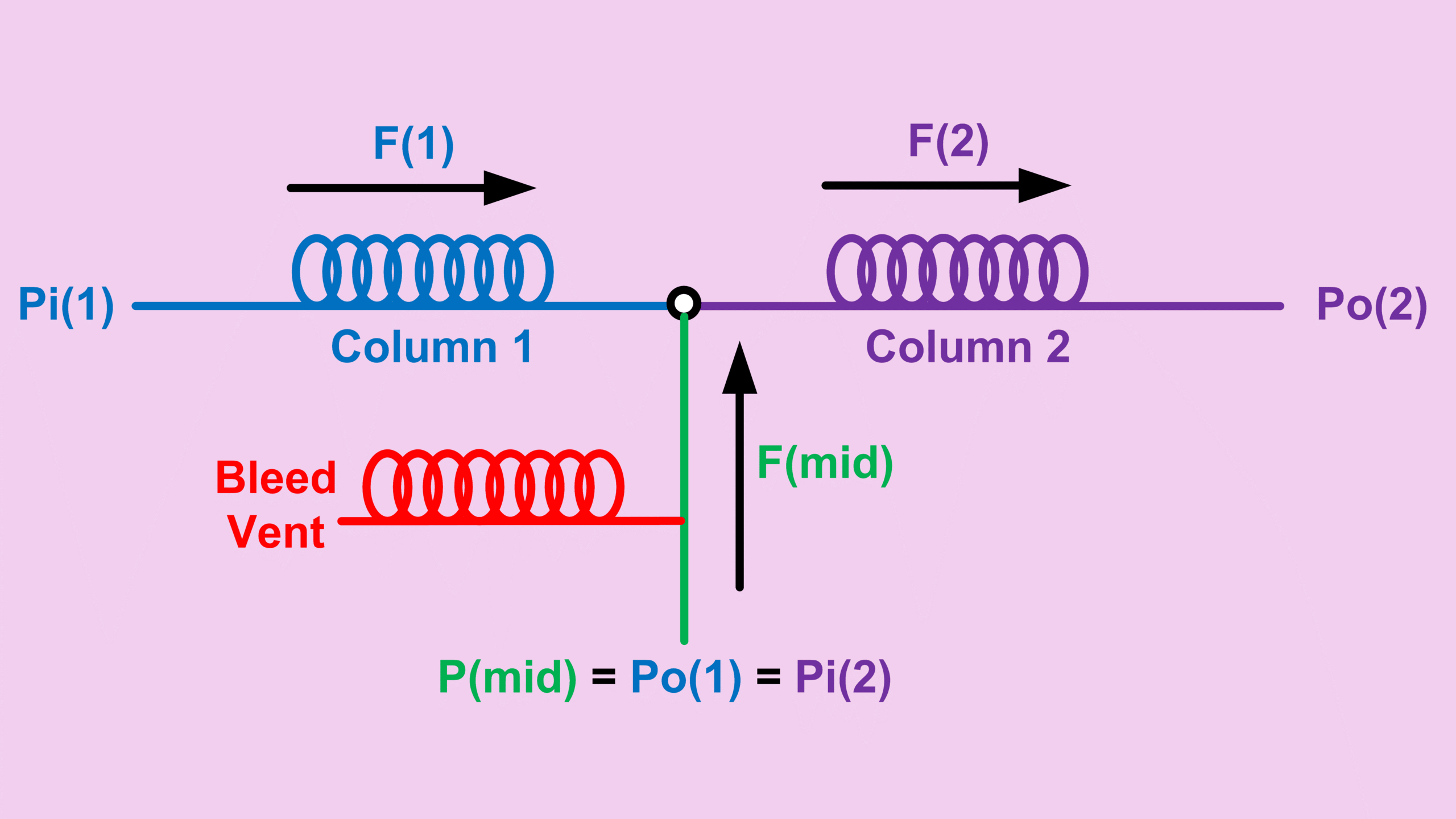
Some applications do not allow the flow ratio to stay below 80%. In such cases, one possible solution is installing a bleed vent for the midpoint pressure line.
Before the midpoint supply enters the connection between column 2 and column 3, the line is teed off with a restrictor that bleeds away excess pressure.
Since the newer Agilent 8890 model, users can purchase a PDS module that includes this bleed vent arrangement. The bleed vent can also be controlled directly through the GC software.
Determining the Pressure Between Column 1 and Column 2
Knowing $F_{(1-2)}$, we also know:
\[ F_{(1-2)}=F_1=F_2 \]With $F_1$ and $R_1$, we can calculate $\Delta P_{1}^2$ from the foundation formula:
\[ F_1=Constant\times\frac{\Delta P_1^2}{R_1} \]Since:
\[ \Delta P_1^2=P_{i(1)}^2-P_{o(1)}^2 \]We can now calculate $P_{o(1)}$, which is the midpoint pressure between column 1 and column 2.
Midpoint Pressure GC Calculator
I put all these calculations together into this calculator:
GC 3-Series Outlet Midpoint Pressure Calculator
You only need to enter:
- Column 1 information
- Column 2 information
- Column 3 information
- Carrier gas
- Column 1 inlet pressure
- Column 3 outlet pressure
- Midpoint pressure
The calculator will then determine the required flows and pressure relationships automatically.
Key Takeaways
- A midpoint pressure GC configuration allows additional pressure control between columns.
- Flow ratio is critical for pressure stability.
- Keeping the flow ratio below 0.8 helps avoid pressure buildup.
- Bleed vents can help stabilize difficult configurations.
- Resistance and pressure relationships make it possible to predict flows accurately.
Continue Exploring GC Flow Configurations
If you are working with complex GC column arrangements, understanding how flow and pressure interact can save a lot of troubleshooting time later.
If you are looking for flow calculation in different column connection configurations, check out the posts below:
- Single column → Column Flow Calculation in GC: From Equation to Practical Use
- Two columns in series → GC Column Series Calculation: How Flow and Pressure Work Across Two Columns
- Three columns in series → GC Column Flow Series for 3 Columns Explained
- Two columns in series with mid-supply → GC Backflush Column Setup Explained (Flow Calculation Made Simple)
- Three columns in series with mid-supply between column 1 and 2 → GC Series Columns with Midpoint Pressure Supply Calculation